Zebra® Carbon Connectors
Additional options for Zebra® Carbon Connectors are available Here.
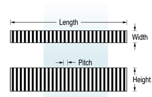
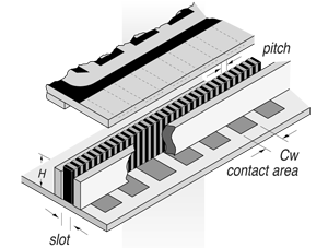
FUJIPOLY connectors (see figure 1) have alternating layers ZEBRA® of conductive carbon-filled and non-conductive silicone rubber. They make reliable connections by being deflected between contacting surfaces. ZEBRA® connectors are used for connecting any LCD from small displays for watches to large area displays for instruments. Table A shows the different types of ZEBRA® connectors available. Table C shows performance characteristics.
Figure 1 shows the three dimensions of the ZEBRA® connector. When ordering, the three dimensions should be specified within the limits shown in table B.
For best overall performance, ZEBRA® connectors must be ordered and used with a ratio of H/W equal to or greater than 1.5.

TABLE A
| LCD contact spaceing center-to-center | Pitch: Sum of the Thickness of an Adjacent Conductive and Non-conductive Layer | Conductive Layers per inch | Individual Conductive and Insulating Layer Thickness | Available Lengths | |||
|---|---|---|---|---|---|---|---|
| Series | Minimum | Nominal | Maximum | Minimum | Minimum | Maximum | Maximum |
| 1002 (CZ410/CZ710) | 0.015 in. 0.38 mm | 0.004 in. 0.10 mm | 0.006 in. 0.15 mm | 240 | 0.001 in. 0.025 mm | 0.004 in. 0.10 mm | 9.0 in. 230 mm |
| 2004 (CZ418) | 0.020 in. 0.50 mm | 0.007 in. 0.18mm | 0.010 in. 0.25 mm | 140 | 0.002 in. 0.050 mm | 0.006 in. 0.15 mm | 9.0 in. 230 mm |
| 2005 (CZ405/CZ705) | 0.010 in. 0.25 mm | 0.002 in. 0.050 mm | 0.004 in. 0.10 mm | 500 | 0.0004 in. 0.010 mm | 0.0024 in. 0.060 mm | 9.0 in. 230 mm |
TABLE B
| Measurement | Tolerance (inches/mm) |
|---|---|
| Length=L | 0.157 in. to 2.40 in. — ± 0.008 in. ……………./……………. 4.00 mm to 61.00 mm — ± 0.20 mm 2.410 in. to 6.00 in. — ± 0.015 in. ……………./……………. 61.2 mm to 152.4 mm — ± 0.38 mm 6.010 in. to 7.87 in. — ± 0.020 in. ……………./……………. 152.6 mm to 200.0 mm — ± 0.50 mm |
| Height=H | 0.020 in. to 0.750 in. ± 0.005 in. ……………/……………. 0.50 mm to 19mm ± 0.127 mm |
| Width=W | 0.015 in. to 0.039 in. — ± 0.002 in………………/…………….. 0.38 mm to 1.0 mm — ± 0.050 mm 0.040 in. to 0.079 in. — ± 0.003 in………………/…………….. 1.01 mm to 2.0 mm — ± 0.076 mm 0.080 in. to 0.118 in. — ± 0.005 in………………/…………….. 2.01 mm to 3.0 mm — ± 0.127 mm above 0.118 in./3.00 mm consult factory. |
TABLE C
| Temperature Range | Current Carrying Capacity 0.040” x 0.040” pad | Resistance Between Layers | ||
|---|---|---|---|---|
| Minimum | Maximum | |||
| Carbon | -40°F -40°C | 212°F 100°C | 0.005 amps | 1012 ohms |


ZEBRA® Connector Dimensions
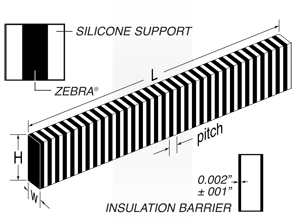
Figure 2 shows the three dimensions of the ZEBRA® connector. When ordering, the three dimensions should be specified within the limits shown in Table B. For best overall performance, ZEBRA® connectors must be ordered and used with a ratio of H/W equal to or greater than 1.5. Details show silicone support (left) and insulation barrier (right). Each is available on one or both sides. Configurations may also include support on one side and insulation on the other.
ZEBRA® CONNECTOR INSULATING BARRIER
| Description | Insulating Barrier |
| Color (one only) | White |
| Hardness, Durometer A | 30 |
| Dielectric Strengtd volts/mil. | 500 |
| Resistance, ohms | 1012 |
| Insulating Barrier Widtd (B) in.* (B) mm | 0.002 ± 0.001 0.050 ± 0.025 |
ABLE D *The tolerance of W1 is equal to the sum of the tolerances of W.
Nominal Resistance Calculation
To calculate the resistance of the ZEBRA® connector use the following formulas:
Where:
Cw = Contact pad width in inches
H = ZEBRA® connector height in inches
W = ZEBRA® connector width in inches
Metric:
| R = | 60 x H |
| Ew x W |
Inches:
| R = | 2.37 x H |
| Ew x W |
Where:
R = Resistance (Ω)
Ew = Electrode Pad width (mm or inches)
W = Connector width (mm or inches)
H = Connector height (mm or inches)
Metric:
F(N) = [(9 x D x W1 xL) + {2.2 x D x (W-W1) x L}] x 9.8 x 10⁻³
Inches:
F(N) = [(5806 x D x W1 x L) + {1419 x D x (W-W1) x L}] x 9.8 x 10⁻³
Nominal Force Deflection Plain ZEBRA® or Insulation Barrier Type
ZEBRA® connectors should be deflected 5% to 25% of H. To calculate F-Force for deflection, use the following formula:
Where:
F = Force (N)
| D = | H-H1 x 100% |
| H |
H = Height of connector (mm or inches)
H1 = Deflected height of connector (mm or inches)
W = Width of connector (mm or inches)
W1 = Width of ZEBRA portion (mm or inches)
L = Length of connector (mm or inches)
Metric:
F(N) = 9 x D x W x L x 9.8 x 10⁻³
Inches:
F(N) = 5806 x D x W x L x 9.8 x 10⁻³
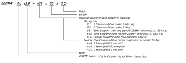
Part Number and Nomenclature:
To specify a connector to your exact requirements, substitute the metric measurements for width, length and height according to instructions below; example part# Ag(2.0 IB1 x 20 x 2.0)-U;

